In this article, we connect an KY-009 RGB LED to an Arduino Uno
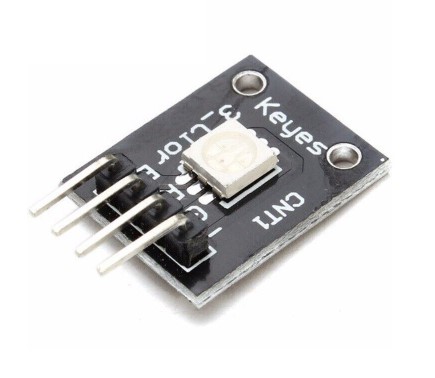
The KY-009 RGB Full Color LED module emits a range of colors by mixing red, green, and blue light. Each color is adjusted by using PWM.
This module consists of a 5050 SMD LED and a 4 pin header.
| Operating Voltage | 5V max Red 1.8V ~2.4V Green 2.8V ~ 3.6V Blue 2.8V ~ 3.6V |
| Forward Current | 20mA ~ 30mA |
| Operating Temperature | -25°C to 85°C [-13°F ~ 185°F] |
| Board Diemsions | 18.5mm x 15mm [0.728in x 0.591in] |
Parts Required
You can connect to the module using dupont style jumper wire.
This should work with other Arduino board – I have tried an Uno and Mega
| Name | Link | |
| Arduino Uno |  |
|
| 37 in one sensor kit |  |
|
| Connecting cables |  |
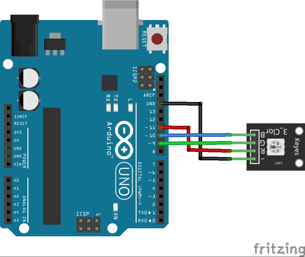
Schematic/Connection
Depending on the input voltage, series resistors are required.
| Series resistor (3.3 V) [Red] | 180 Ω |
| Series resistor (3,3 V) [Green] | 100 Ω |
| Series resistor (3,3 V) [Blue] | 100 Ω |
| Series resistor (5 V) [Red] | 180 Ω |
| Series resistor (5 V) [Green] | 100 Ω |
| Series resistor (5 V) [Blue] | 100 Ω |
I omitted these in this connection diagram
Code Example
Pulse width modulation [PWM] can be used to regulate the brightness of an LED – in this process, the LED is switched on and off at specific time intervals, with the ratio of the switch-on and switch-off times corresponding to a relative brightness.
int redpin = 11;    // select the pin for the red LED
int bluepin =10;   //select the pin for the blue LED
int greenpin =9; //select the pin for the green LED
int val;

void setup()
{
  pinMode(redpin, OUTPUT);
  pinMode(bluepin, OUTPUT);
  pinMode(greenpin, OUTPUT);
  Serial.begin(9600);
}

void loop()
{

for(val=255; val>0; val--)
{
   analogWrite(11, val);
   analogWrite(10, 255-val);
   analogWrite(9, 128-val);
   delay(1);
}

for(val=0; val<255; val++)
{
   analogWrite(11, val);
   analogWrite(10, 255-val);
   analogWrite(9, 128-val);
   delay(1);
}

  Serial.println(val, DEC);
}
You can also use
int RedLed = 11;
int Blueled = 10;
int GreenLed = 9;

void setup ()
{
  // Initialize output pins for the LEDs
  pinMode (RedLed, OUTPUT);
  pinMode (GreenLed, OUTPUT);
  pinMode (Blueled, OUTPUT);
}

void loop ()
{
  digitalWrite (RedLed, HIGH); // LED is switched on
  digitalWrite (GreenLed, LOW); // LED is switched on
  digitalWrite (Blueled, LOW); // LED is switched on
  delay (1000);

  digitalWrite (RedLed, LOW); // LED is switched on
  digitalWrite (GreenLed, HIGH); // LED is switched on
  digitalWrite (Blueled, LOW); // LED is switched on
  delay (1000);

  digitalWrite (RedLed, LOW); // LED is switched on
  digitalWrite (GreenLed, LOW); // LED is switched on
  digitalWrite (Blueled, HIGH); // LED is switched on
  delay (1000);
}
Serial Monitor Output
N/A
Links
https://github.com/getelectronics/ArduinoCode/tree/main/37%20Sensor%20Kit/KY-009_SMD_RGB