A rotary encoder, also called a shaft encoder, is an electro-mechanical device that converts the angular position or motion of a shaft or axle to an analog or digital code.
There are two main types: absolute and incremental (relative). The output of absolute encoders indicates the current position of the shaft, making them angle transducers. The output of incremental encoders provides information about the motion of the shaft, which is typically further processed elsewhere into information such as speed, distance and position.
Rotary encoders are used in many applications that require precise shaft unlimited rotation—including industrial controls, robotics, special purpose photographic lenses,[1] computer input devices (such as optomechanical mice and trackballs), controlled stress rheometers, and rotating radar platforms.
An incremental encoder works differently by providing an A and a B pulse output that provide no usable count information in their own right. Rather, the counting is done in the external electronics. The point where the counting begins depends on the counter in the external electronics and not on the position of the encoder. To provide useful position information, the encoder position must be referenced to the device to which it is attached, generally using an index pulse. The distinguishing feature of the incremental encoder is that it reports an incremental change in position of the encoder to the counting electronics
An incremental rotary encoder provides cyclical outputs (only) when the encoder is rotated. They can be either mechanical, optical or magnetic. The mechanical type requires debouncing and is typically used as digital potentiometers on equipment including consumer devices. Most modern home and car stereos use mechanical rotary encoders for volume control. Due to the fact the mechanical switches require debouncing, the mechanical type are limited in the rotational speeds they can handle. The incremental rotary encoder is the most widely used of all rotary encoders due to its low cost and ability to provide signals that can be easily interpreted to provide motion related information such as velocity.
The fact that incremental encoders use only two sensors does not compromise their resolution. One can find in the market incremental encoders with up to 10,000 counts per revolution, or more.
There can be an optional third output: reference or “index”, which happens once every turn. This is used when there is the need of an absolute reference, such as positioning systems. The index output is usually labeled Z.
The optical type is used when higher speeds are encountered or a higher degree of precision is required.
Incremental encoders are used to track motion and can be used to determine position and velocity. This can be either linear or rotary motion. Because the direction can be determined, very accurate measurements can be made.
They employ two outputs called A & B, which are called quadrature outputs, as they are 90 degrees out of phase.
The state diagram:
|
|

The two output wave forms are 90 degrees out of phase, which is what quadrature means. These signals are decoded to produce a count up pulse or a count down pulse. For decoding in software, the A & B outputs are read by software, either via an interrupt on any edge or polling, and the above table is used to decode the direction. For example, if the last value was 00 and the current value is 01, the device has moved one half step in the clockwise direction. The mechanical types would be debounced first by requiring that the same (valid) value be read a certain number of times before recognizing a state change.
On encoders with detents there are different ways to switch states. In some, both A and B are always open circuit at the detents, and an entire 00 → 00 switching cycle occurs while transitioning from one detent to the next. Others have detents of alternating 00 and 11 value, with staggered switching times during the transition between detents.

Additionally some incremental encoders output a “Z” signal. Once every rotation, this Z signal is rising for typically 90°, on exactly the same position. This can be used as an accurate reference point. Some incremental encoders also have additional differential signals, called “/A”, “/B” and “/Z”. These signals are inverted “A”, “B” and “Z” signals. Controllers can compare each pair (“A” must be equal to inverted “/A”) to ensure that there is no error during the transmission.[10]
An observer, such as a microprocessor, will read (sample) the output of the encoder. The observer needs to sample the encoder output often enough so it does not miss any code changes. If the encoder turns too fast, then the observer may miss an encoder output change, so the observer will see an invalid transition, such as 00 → 11, and be confused. For that transition, the observer does not know which way the encoder turned: it may have gone forward (00 → 01 → 11) or backward (00 → 10 → 11). If the encoder is turning even faster, then multiple output changes could be missed, and the observer may get the direction wrong. Consider the moving forward sequence 00 → 01 → 11 → 10 (3 steps forward). If the encoder is turning too fast, the observer may see only the first (00) and fourth (10) outputs and conclude the encode made a legal 00 → 10 transition (1 step backward).
This same principle is used in ball mice to track whether the mouse is moving to the right/left or forward/backward.
Rotary encoders with a single output (i.e. pulsers) cannot be used to sense direction of motion. They are well-suited for systems that measure rate-of-movement variables. In certain applications they may be used to measure distance of motion (e.g. feet of movement).
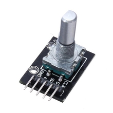
Here is a module that I used

Connection
Module CLK -> Arduino D2
Module DT -> Arduino D3
Module + -> Arduino 5v
Module GND -> Arduino GND
Code
I tried many examples which had several problems such as incorrectly determining the direction and missing turns and double counts but the following example seemed to work fine, so kudos to the author
[codesyntax lang=”cpp”]
/*******Interrupt-based Rotary Encoder Sketch*******
by Simon Merrett, based on insight from Oleg Mazurov, Nick Gammon, rt, Steve Spence
*/

static int pinA = 2; // Our first hardware interrupt pin is digital pin 2
static int pinB = 3; // Our second hardware interrupt pin is digital pin 3
volatile byte aFlag = 0; // let's us know when we're expecting a rising edge on pinA to signal that the encoder has arrived at a detent
volatile byte bFlag = 0; // let's us know when we're expecting a rising edge on pinB to signal that the encoder has arrived at a detent (opposite direction to when aFlag is set)
volatile byte encoderPos = 0; //this variable stores our current value of encoder position. Change to int or uin16_t instead of byte if you want to record a larger range than 0-255
volatile byte oldEncPos = 0; //stores the last encoder position value so we can compare to the current reading and see if it has changed (so we know when to print to the serial monitor)
volatile byte reading = 0; //somewhere to store the direct values we read from our interrupt pins before checking to see if we have moved a whole detent

void setup() {
  pinMode(pinA, INPUT_PULLUP); // set pinA as an input, pulled HIGH to the logic voltage (5V or 3.3V for most cases)
  pinMode(pinB, INPUT_PULLUP); // set pinB as an input, pulled HIGH to the logic voltage (5V or 3.3V for most cases)
  attachInterrupt(0,PinA,RISING); // set an interrupt on PinA, looking for a rising edge signal and executing the "PinA" Interrupt Service Routine (below)
  attachInterrupt(1,PinB,RISING); // set an interrupt on PinB, looking for a rising edge signal and executing the "PinB" Interrupt Service Routine (below)
  Serial.begin(115200); // start the serial monitor link
}

void PinA(){
  cli(); //stop interrupts happening before we read pin values
  reading = PIND & 0xC; // read all eight pin values then strip away all but pinA and pinB's values
  if(reading == B00001100 && aFlag) { //check that we have both pins at detent (HIGH) and that we are expecting detent on this pin's rising edge
    encoderPos --; //decrement the encoder's position count
    bFlag = 0; //reset flags for the next turn
    aFlag = 0; //reset flags for the next turn
  }
  else if (reading == B00000100) bFlag = 1; //signal that we're expecting pinB to signal the transition to detent from free rotation
  sei(); //restart interrupts
}

void PinB(){
  cli(); //stop interrupts happening before we read pin values
  reading = PIND & 0xC; //read all eight pin values then strip away all but pinA and pinB's values
  if (reading == B00001100 && bFlag) { //check that we have both pins at detent (HIGH) and that we are expecting detent on this pin's rising edge
    encoderPos ++; //increment the encoder's position count
    bFlag = 0; //reset flags for the next turn
    aFlag = 0; //reset flags for the next turn
  }
  else if (reading == B00001000) aFlag = 1; //signal that we're expecting pinA to signal the transition to detent from free rotation
  sei(); //restart interrupts
}

void loop(){
  if(oldEncPos != encoderPos) {
    Serial.println(encoderPos);
    oldEncPos = encoderPos;
  }
}
[/codesyntax]
Link
 KY-040 Rotary Decoder Encoder Module For Arduino