In this example we will program an Attiny44 using an Arduino – you have already seen how to add support for these microcontrollers at Adding ATtiny support in theArduino IDE lets take it one step forward using the Attiny44
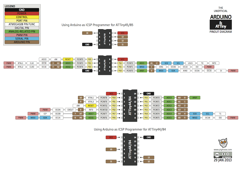
The first step is to take a look at the pinouts and features available if you decide to use an Attiny44, the diagram below displays this just nicely, as you can see there is less I/O but you still get PWM, I2C and analogue in capabilities. For smaller projects this may be just what you need. The experimenter in me still likes to build my own micro boards with various electronic components attached.
You’ll notice the Attiny44 has 8 analog pins, 10 I/O pins, I2C capabilitoes, SPI and 4 PWM pins. So its a fairly powerful little chip.
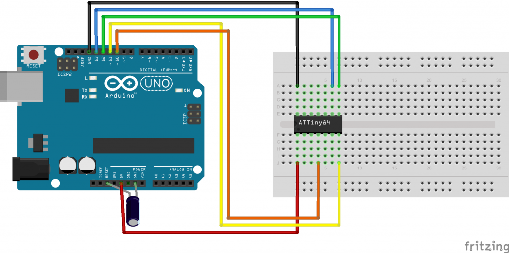
As always you have to connect your Attiny44 to your Arduino, here are the necessary connections
- Connect the ATtiny44 Pin 1 to 5 volts (VCC)
- Connect the ATtiny44 Pin 14 to ground.
- RESET: Connect the ATtiny44 Pin 4 (Reset) to Arduino Pin 10.
- MOSI: Connect the ATtiny44 Pin 7 to Arduino Pin 11.
- MISO: Connect the ATtiny44 Pin 8 to Arduino Pin 12.
- CLOCK: Connect the ATTiny44 Pin 9 to Arduino Pin 13
You may need to connect a 10uF capacitor between Gnd and the Arduino Reset pin. the anode goes to the Arduino gnd pin
Here is a layout for you to get a better idea (NOTE I MADE A MESS OF THE CAPACITOR, ITS REVERSED)
I had to use the boards that were installed using https://github.com/damellis/attiny, using Arduino 1.6.7 you can add support by using the Board Manager – https://raw.githubusercontent.com/damellis/attiny/ide-1.6.x-boards-manager/package_damellis_attiny_index.json.
We discussed how to enable these microcontrollers in a previous tutorial using Arduino IDE 1.6.4 and onwards
You can see my settings for the Attiny44 in the screenshot below, this is in the Tools menu
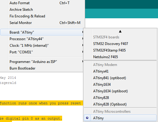
The key ones are select the correct processor and make sure the clock is 8Mhz internal.
I would recommend you burn the bootloader, you can see that above
Code
Refer to the diagram earlier, we will flash an LED connected to Pin 13
[codesyntax lang=”cpp”]
// the setup function runs once when you press reset or power the board
void setup()
{
  // initialize digital pin 0 as an output.
  // Attiny44 pin 13
  pinMode(0, OUTPUT);
}

// the loop function runs over and over again forever
void loop()
{
  digitalWrite(0, HIGH);   // turn the LED on (HIGH is the voltage level)
  delay(1000);              // wait for a second
  digitalWrite(0, LOW);    // turn the LED off by making the voltage LOW
  delay(1000);              // wait for a second
}
[/codesyntax]